Restoring a 1940 Philco dial
scale
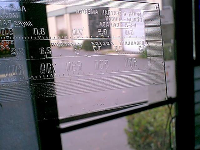
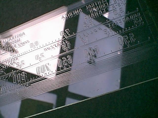 With most of the paint already flaked off, I
found that the glass was molded or etched, So, I decided to try a
technique that worked well on an auto radio dial. Basically,
I used Testors (tm) model paint, and squeegee'd it on with a razor
blade. Keeping up even pressure, I wanted to only have a slight film
left on the clear areas... When the paint had dried, I went back with a
new razor blade, and carefully scraped the glass to remove the last of
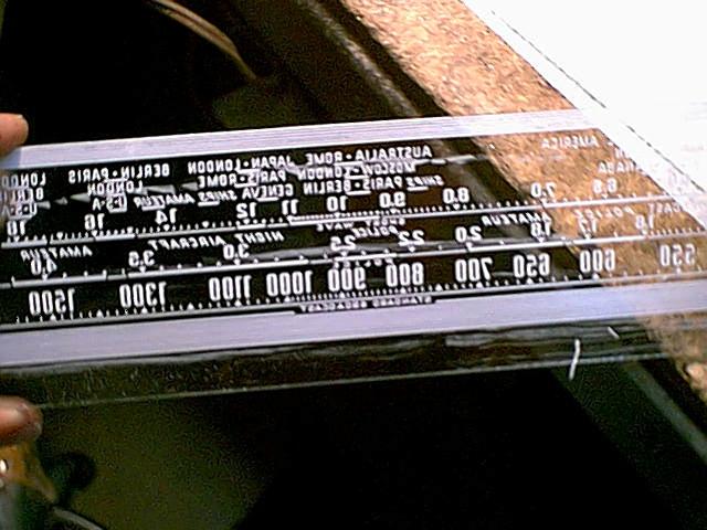
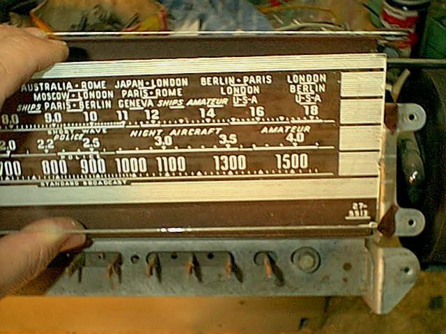
the film. It didn't take all that long... Pic 3 shows the dial almost
done. Pic 4 is just before final cleanup of a few rough areas, and
re-installation.
With most of the paint already flaked off, I
found that the glass was molded or etched, So, I decided to try a
technique that worked well on an auto radio dial. Basically,
I used Testors (tm) model paint, and squeegee'd it on with a razor
blade. Keeping up even pressure, I wanted to only have a slight film
left on the clear areas... When the paint had dried, I went back with a
new razor blade, and carefully scraped the glass to remove the last of
the film. It didn't take all that long... Pic 3 shows the dial almost
done. Pic 4 is just before final cleanup of a few rough areas, and
re-installation.
PC mount style
electrolytic cap replacement.
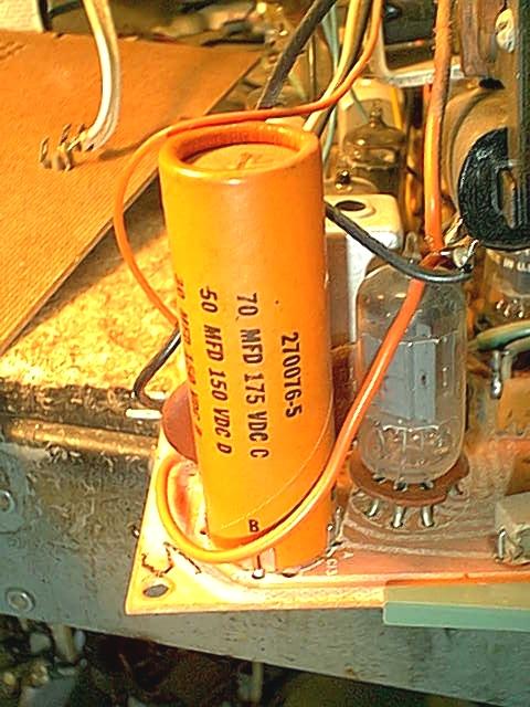
 This can be problematical on
some sets, I've seen a few not so good ideas on how to replace these.
This is the method I use, it works well in most cases. Photo 1. The
offending electrolytic. This is a 3 section. , 100, 47, 33 @ 160V.
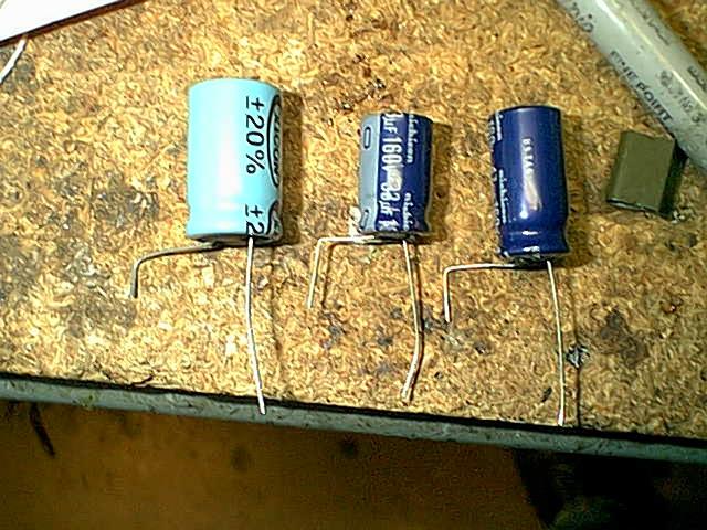
Photo 2. the replacements, pre-fabbed. the NEGATIVE lead
This can be problematical on
some sets, I've seen a few not so good ideas on how to replace these.
This is the method I use, it works well in most cases. Photo 1. The
offending electrolytic. This is a 3 section. , 100, 47, 33 @ 160V.
Photo 2. the replacements, pre-fabbed. the NEGATIVE lead
is bent right at the base, and again equating to the distance between
the original cap's holes on the PCB. Most original caps have some sort
of
legend on them as to which pins are what.. (and hopefully only go in
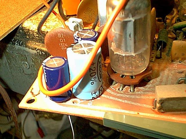
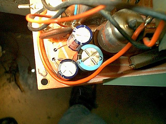
one way) Photo3. Installed. Photo 4. Top view. I could have reversed
the lead bend on the 47uF which would have moved the cap to the left..
Use whatever methodology works best for you... I have had problems on
one
set
where the 'lytic was very close to the arc of the tuning caps
rotor, I had to move the caps slightly to accomodate..
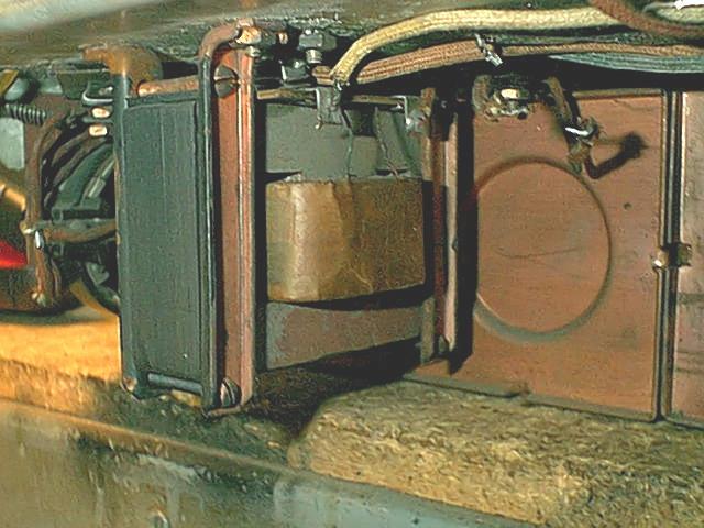
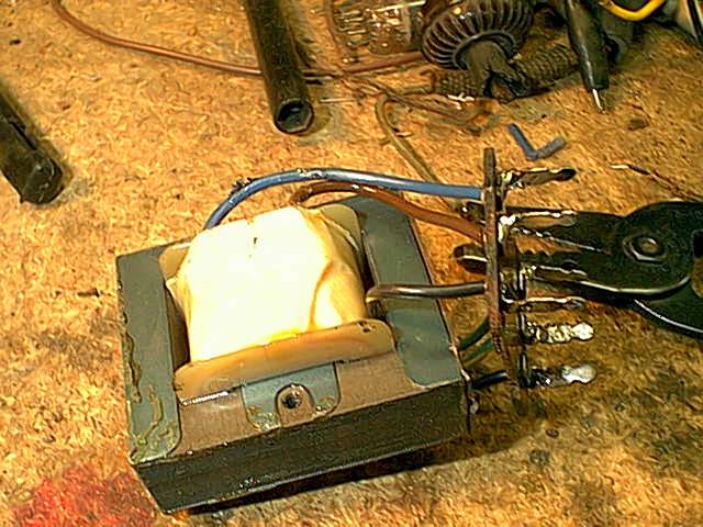
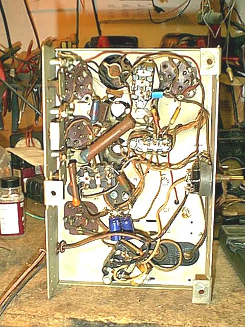
Restuffing a Philco audio interstage
transformer. (38-116)
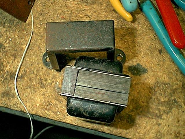
 The transformer. Open
primary, and it's a goofy
dual
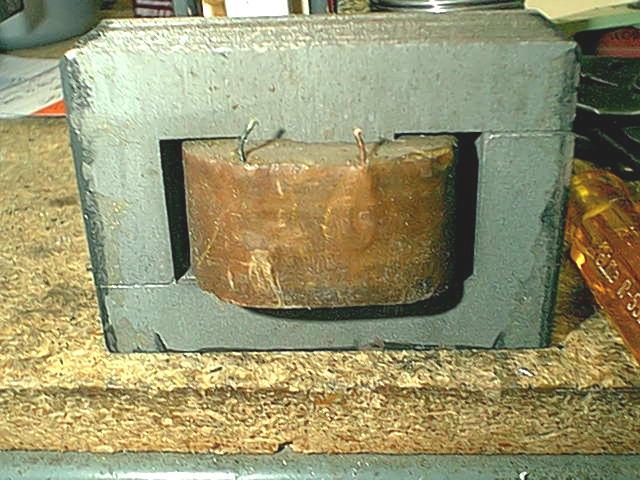
Core removed.
The transformer. Open
primary, and it's a goofy
dual
Core removed.
secondary type, to accomodate the NFB circuitry.
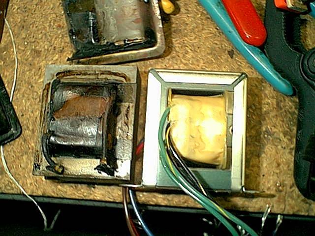
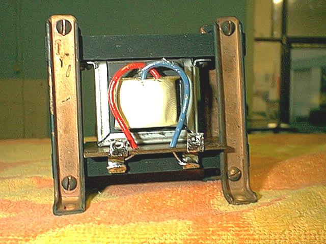
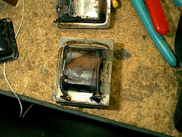
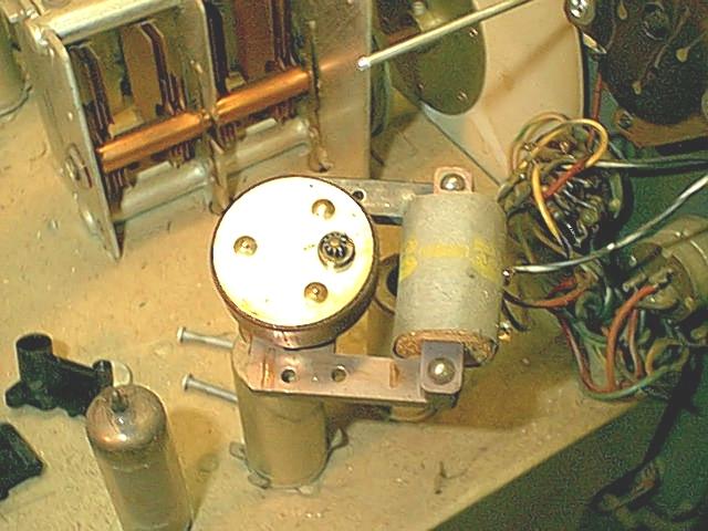
 Alongside a
Hammond 124E. You can see
where
Perfect (almost) fit. Who'd a thunk it? I had to
remove the
Alongside a
Hammond 124E. You can see
where
Perfect (almost) fit. Who'd a thunk it? I had to
remove the
this is
headed..
pasteboard bottom piece to get it all back together.
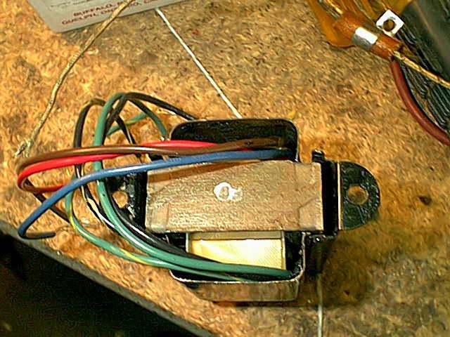
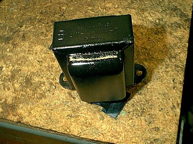 Wired up to
the terminal
lugs.
And painted. the photo looks far worse than the actual result.
Wired up to
the terminal
lugs.
And painted. the photo looks far worse than the actual result.
dunno why.
This transformer sits right in the back of this chassis, in the center,
so highly visible. I didn't want to screw in a modern unit if
I could preserve the looks...
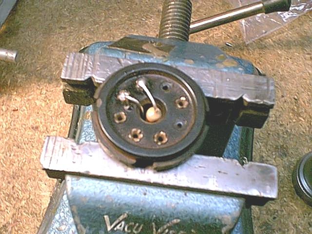
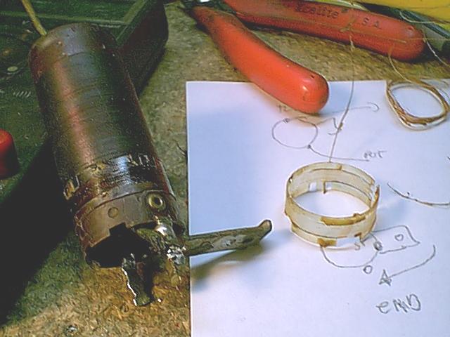
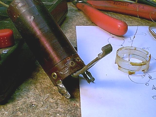
Repairing a Grundig
(Saba, Telefunken, Elbe, etc) "frozen" volume pot.
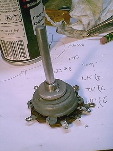
Basically, only one
way to do this really. Some heat, and remove the last remnants of the
glue that used to be grease.
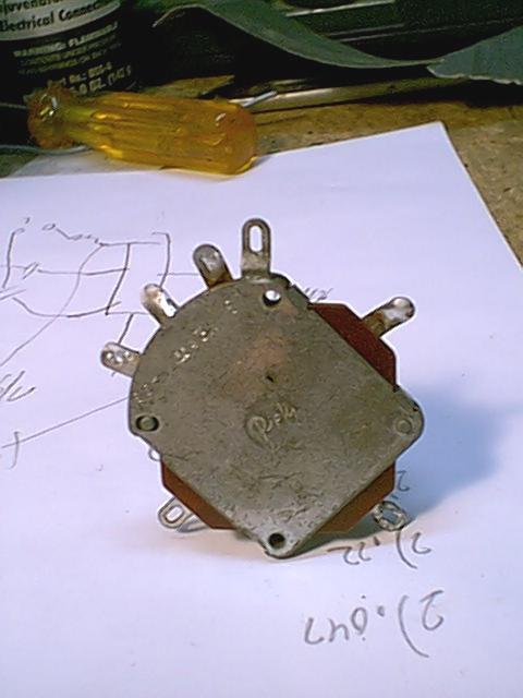
The pot removed. Note the 2 "locator" pins that align the parts. (About
twice the amount of parts you'd think is nessecary)
In the background is the scribble of where all the wires went. Pic 2.
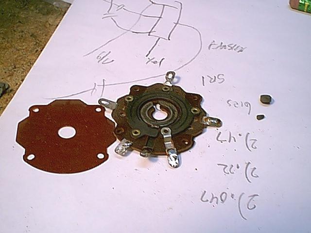
Some of the parts laid out in the order they came out.
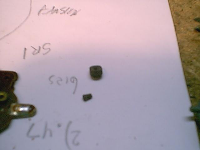
Pic 3. The carbon contacts. These will fall out when you remove the
back, DON'T loose them. Pic 4. With some heat applied, the shaft is
removed. That plate with the 2 ears on it is the shaft retainer, you
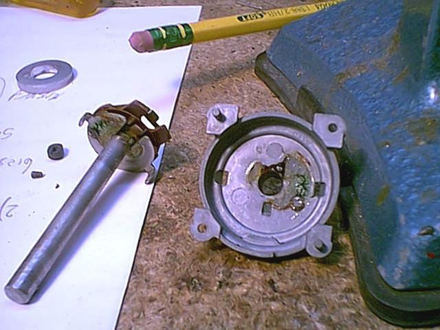
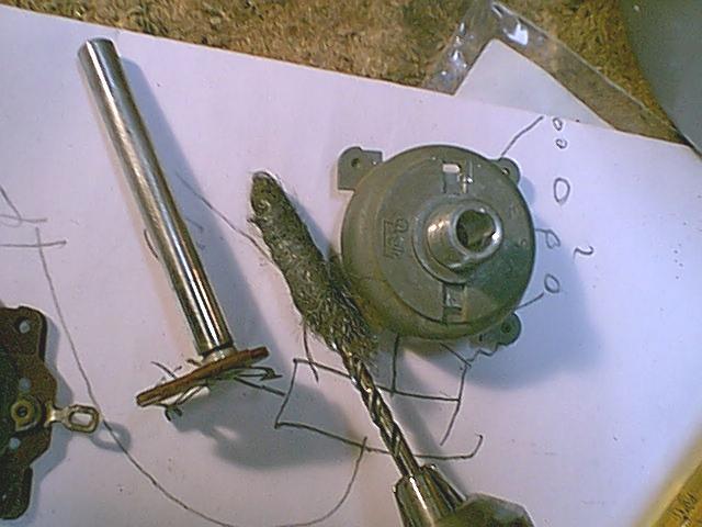
have to bend those ears up to get the shaft out. Pic 5. The favorite
tool for removing the hardened gack from the shaft and bushing is some
steel wool. A bit wrapped on a drill bit makes short work of the
bushing. Pic 6. Clean the carbon track and metal ring (Pic 2), Lube and
re-assemble. The most difficult part is getting the carbon buttons to
sit where they're supposed to. Some pots only have 1 (the conic
section) This one has 2. As the whole mess is held together with small
bent metal tabs, you won't get many repeats of this performance.
Making a
replacement ballast.
(300mA filament string)
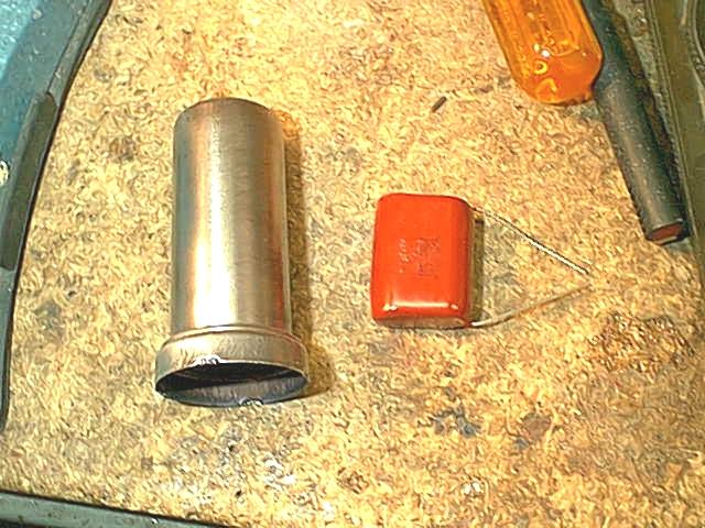
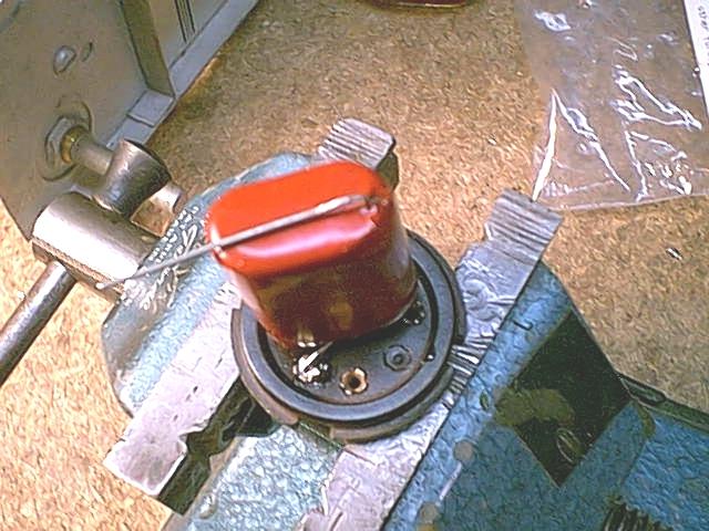
This ballast is for a 300mA
filament string, and 1 pilot lamp.
1. Installing a 39 Ohm 2W resistor. I put this one in the locator,
but thought better of it later and moved it out. Normal operation it
would have been OK, but if the
pilot lamp burns out, this resistor will warm up a
bit. The value was chosen to work with a #47 (or equiv) bulb, so that
if the bulb does burn out, the current
change would not be as great as with a #44
bulb. (From 150 to 300mA vice from 50 to 300mA). Also, I cleaned
the top of the pins, and made the solder
connections there, as well as at the tips. (Belt and
suspenders)
2. The capacitor and can. The cap is an 8.2uF 160VAC rated cap
(Mouser electronics) Anything bigger wouldn't fit, and this one needs a
slight "mod"
3. The "Mod" the leads are torn out partially (and carefully) and
a dab of service cement re-seals the end. This is done to keep them
away from the metal can.
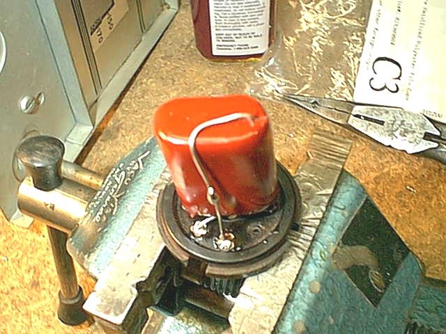
4. Detail of the second connection.
5. A few layers of electrical tape.
6. Well, why not.
7. Installed and working in a Crosley. This value cap gives
near-correct filament voltages, maybe a wee bit low, but with a good
set of tubes the set plays fine.
Also, the "soft start" will likely add to the
longevity of the tubes. Earlier, I had tried "trimming" the voltage
with additional AC rated caps, but it was more messy
than it was worth. The lable identifies it as a
"Capacitor ballast" so that somebody with an Ohmmeter hopefully gives
it a second think...
Repairing a Philco lamp socket
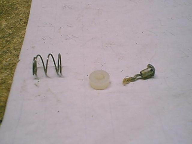
1. The typical problem. The rubber has morphed into a hardened mass, no
pliability left. It can be easily "crunched" off with pliers or cutters.
2. The fix. Rivet and spring from original, and adding a #4 nylon
washer (Mouser Electronics
p/n
)
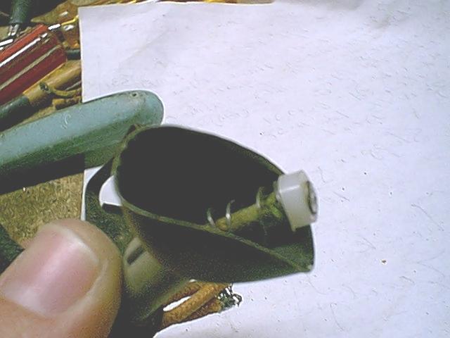
3. Assembled. put the lamp hood, then the spring, then the washer over
the wire. strip just about 1/16" of the end of the wire.
Good idea to tin this now, as the wire sometimes doesn't want to
solder. Place the rivet over the end of the wire and solder.
If the solder is built up too high, you may have to file this down a
little. Done correctly, the rivet butts up against the end of the wire,
and no additional insulation is nessecary. Install the lamp.
4. Several reworked lamp sockets.
The dreaded green dot Philco disease
Or, "Is my
radio doomed?"

1. A little hard to see, but the antenna coil has it. The dreaded
Philco "Green dot" disease. Fortunately, this usually
strikes the untuned primaries of these solonoid
coils, making
the job a bit easier.
2. Unwound, and the celluloid collar removed too. You DID make a
diagram of the wires as you took them off, AND
counted the number of turns, noting the start /
finish, right? Sure, you will remember, but.. Is that the phone ringing?
3. A little heat gun and paper towel action to remove the excess wax
and smooth it out.
4. After applying a layer or so of a strip of packing tape, winding the
same number of turns, in the same direction and
location. (24 1/8 turns, as I recall..) A
little service cement to hold it in place..
5. Viola! Installed and playing. Don't bother to try and align it until
the service cement is totally dry...
1. A nice Bosch "Cruiser 66", and, as with a lot of battery sets,
nothing much wrong with it, other than the audio transformers open
secondaries. (yep, both of them)
2. The removed core. If it had a 1/2 inch center, I'd install a
replacement bobbin from hammond. NO such luck, these are huge.
3. The Hammond replacement, mounted on some precision cut poplar,
painted flat black. Apparently woodworkers don't care for .9" by
3.2"...
4. The disguise.. Actually, it is strips of paper cut from a shopping
bag, and sprayed with clear lacquer, then wound around the modern unit.
Wouldn't fool anybody for long, but at least
maintains the appearence of the original. If I would have gone a bit
further, I would have cut some pieces to
replace the sides of the core.
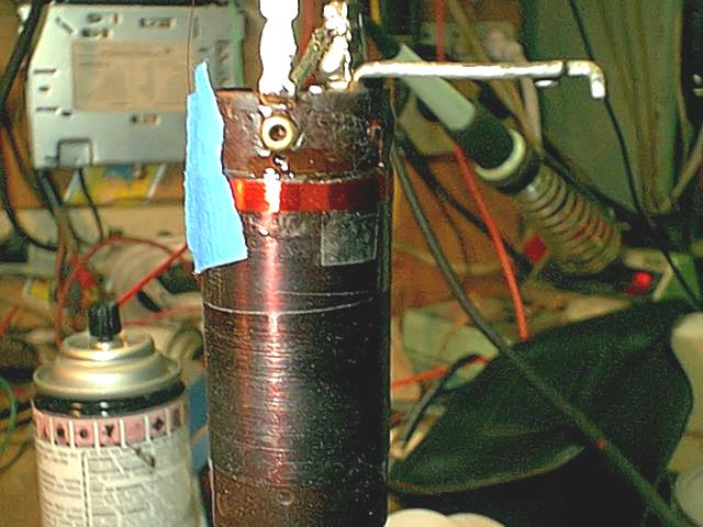
TELECHRON
CLOCK MOTOR REVITALIZATION
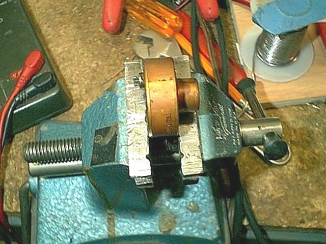
1. Oh no! A dead Telechron clock motor. From the constant heat, etc,
the lube in these can turn into a sorta glue.
2. Ready for surgery...
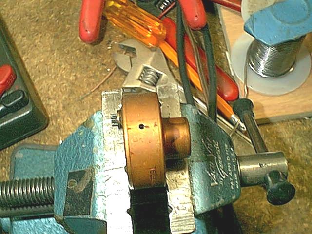
3. The incision. This is made 90 deg. from the exposed pinion. the
copper can drills easily, you can use a "Pin vise" to hold a small
drill bit.
Not too small, or you won't be able to get any
spray solvent in the unit. I usually do this with the motor inverted,
so chips don't get in the mech.
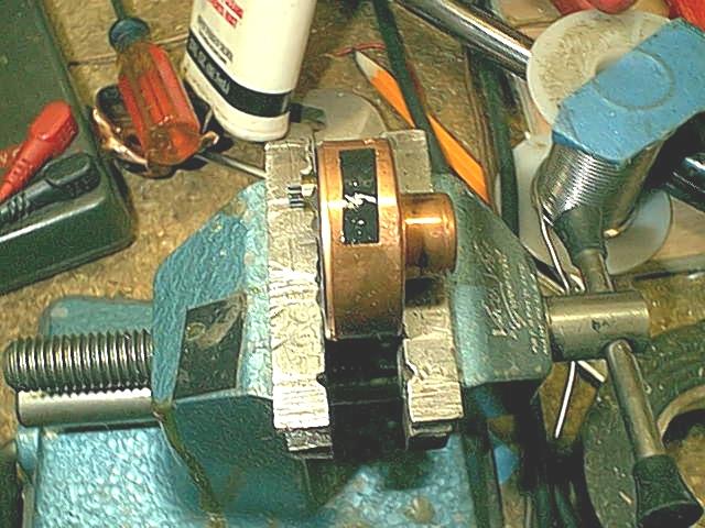
4. Spray in the disolver / cleaner /degreaser of your choice. a few
short squirts should do. Slosh it around for a few minutes.
5. Invert the unit to drain the solvent & crud. This may take a
while. Be sure to get it all out. a little heat helps, too. (very
little)
6. A few drops of 3-n-1 or other light oil in the mech. this should
drip down on the center of the internal mech.
7. You should now be able to get the mech to spin by torquing the
pinion with your fingers. (It isn't easy, but should be moving) It's
tempting to grab
the pinion with a tool, but resist. Some of
these units have phenolic gears for the slower moving parts.
8. Carefully clean and de-grease around the hole. I usually install a
tape patch, backed up with some service cement. In the early days, I
tried soldering
the hole closed, but it was way more trouble than it
was worth..
9. Re-assemble. you did remember where all the bits went, right?
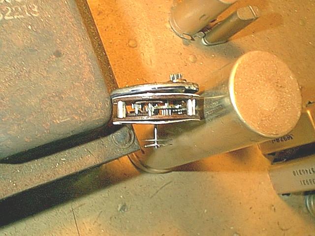
10. For the curious, the last pic shows the "guts" of a unit that was
not repairable. (missing tooth on a phenolic gear)
Making a
replacement "C" band antenna for an RCA K-105
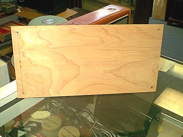
1. The layout. I got the dimension info from a very helpfull source
(John, k9uwa) on rec.antiques.radio+phono newsgroup, that the antenna
was 13" x 6", and that
the leads (8") came off of the middle of
the small dimension.
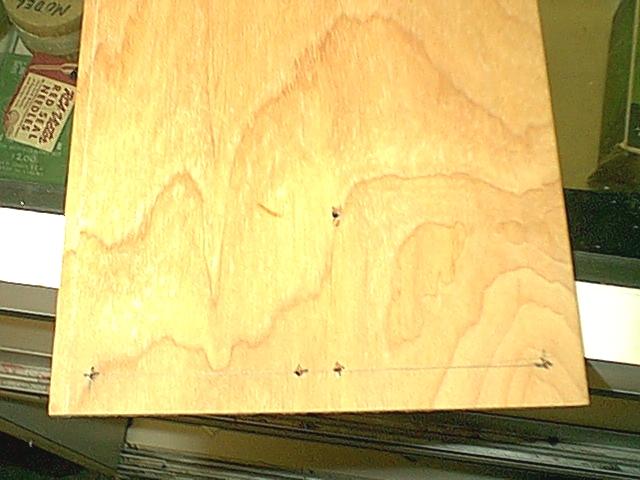
2. Cut a piece of "door skin" (Thin plywood, and usefull for a lot of
radio stuff) to 14 x 7, and placed some holes 1/2" from the corners.
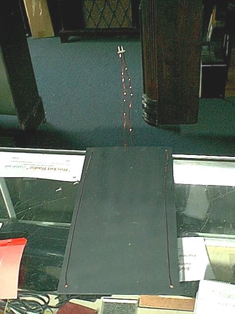
3. Wired and ready for installation
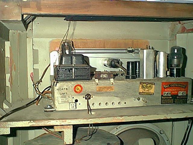
4. Installed, now on to the Alignment..
Making a dial pointer.
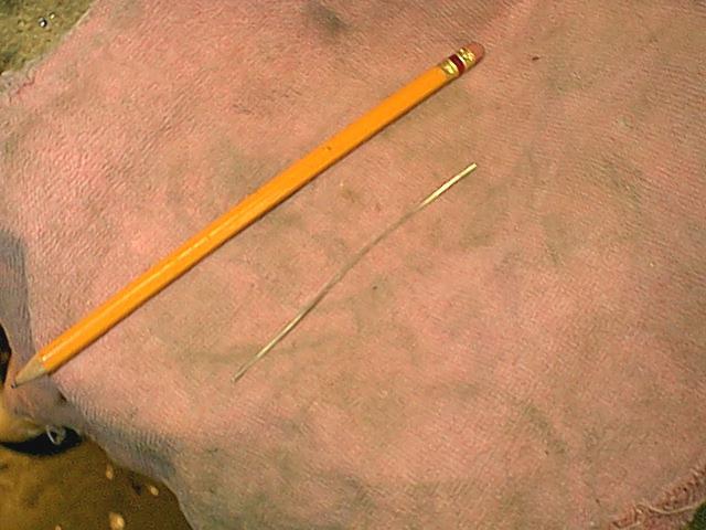
So, the set you're working on is missing the pointer. Not to
worry. This setup is borrowed from the "Hun" sets (Grundig, Saba,
Telefunken, etc..)
1. Yep. Just a piece of heavy bus wire.
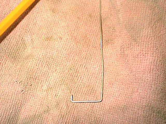
2. The custom tailpiece, and the secret to it's success.
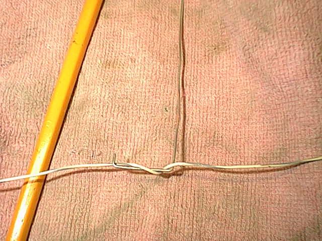
3. A piece of hookup wire showing how the dial cord will be wrapped.
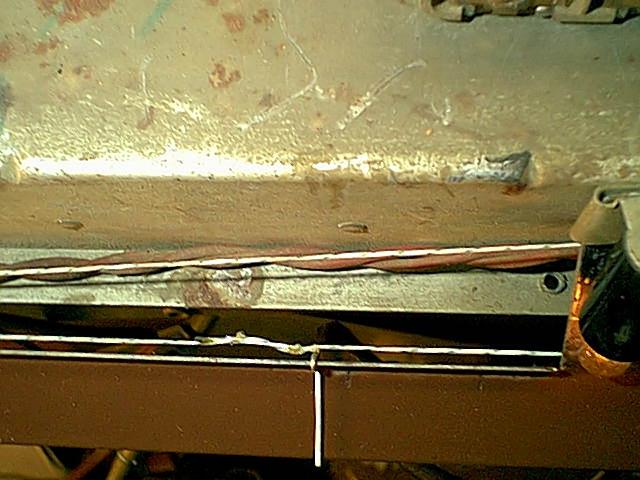
4. Installed on an RCA.
5. Another view. The indicator can be painted, as this is, or a small
piece of colored heat-shrink can be used.
The magic here is that the dial string is supporting
the pointer, with very little help needed from other mechanical aids,
like the tiny sheet metal
piece that the old pointer used to ride. I
start out with the tail piece, and wrap the dial cord. About an inch is
usually sufficient. Then, simply make the
bends you need to get the pointer where it
needs to be, In this case, up about 3/8", over the top, then bent
parallel to the background.
The pointer only barely contacts the edge the
old one rode on. Easy to slide the pointer along the string to get it
aligned, then secure with a drop
of service cement.
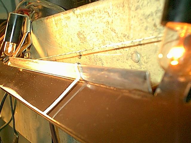
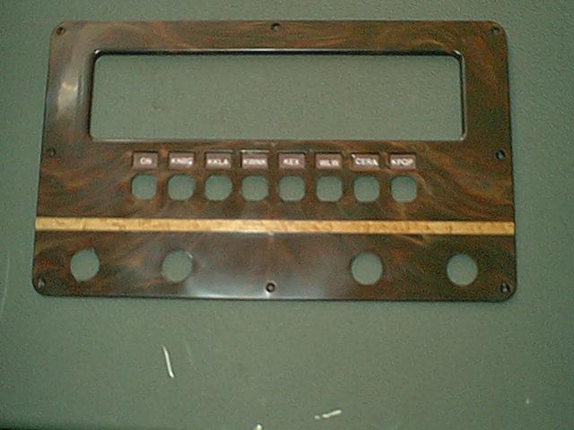
Making a replacement for the brass strip to
go on a repro escutcheon. It looks way better in real life..
A strip of Birdseye maple cut to 1/4
inch,
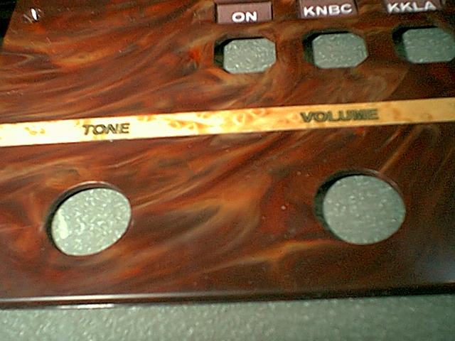
Decals installed (on top of 2 coats of
lacquer)
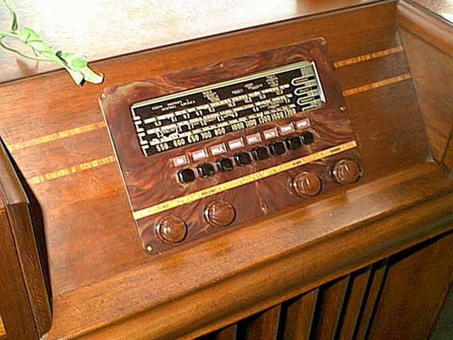
Installed! In retrospect, I should have used something
and sanded to fit
precisely.
2 more coats the next
day.
a little darker, maybe match the existing strips on
each side of the cabinet. Maybe next time...
Faux Filters
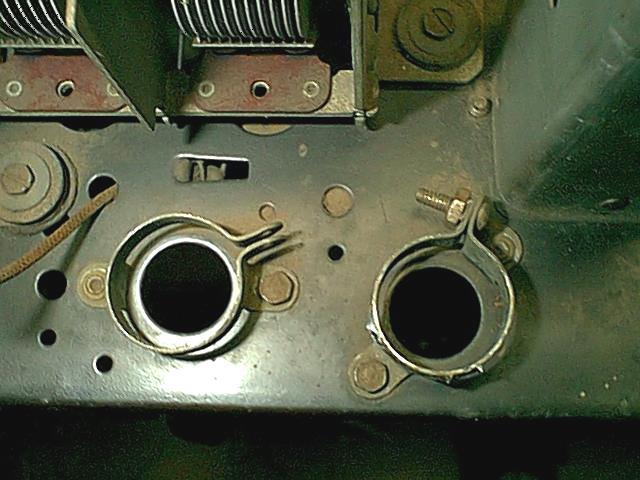
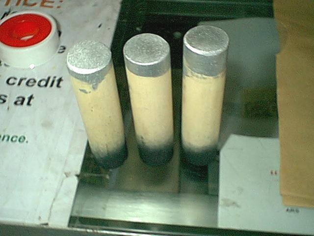
The set is a Stromberg Carlson, missing all 3 filters from a
previous
repair. 1"
dowel rod cut in 4" sections. Aluminum paint on top, flat black on the
bottom.
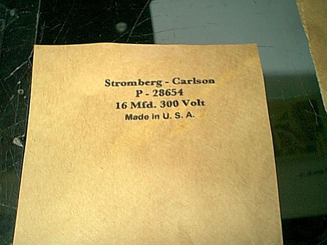
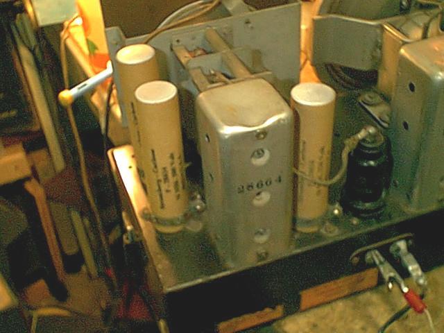
Cover, printed on a piece of paper shopping bag. Then, clear
lacquer.
Installed on dowels with 3M type 77 adhesive, and installed in the set.
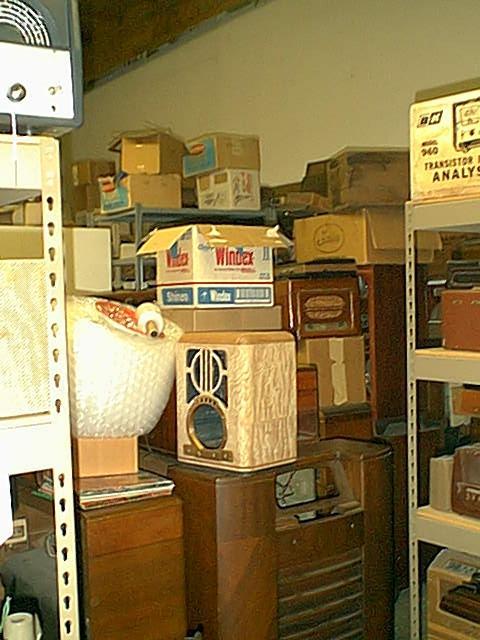
the SHOP
by popular(?!?) request...
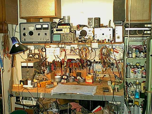
The
Bench. Normally, it doesn't look this
bad.
Tubes, from 0 to 14
Normally, it is much, much worse....
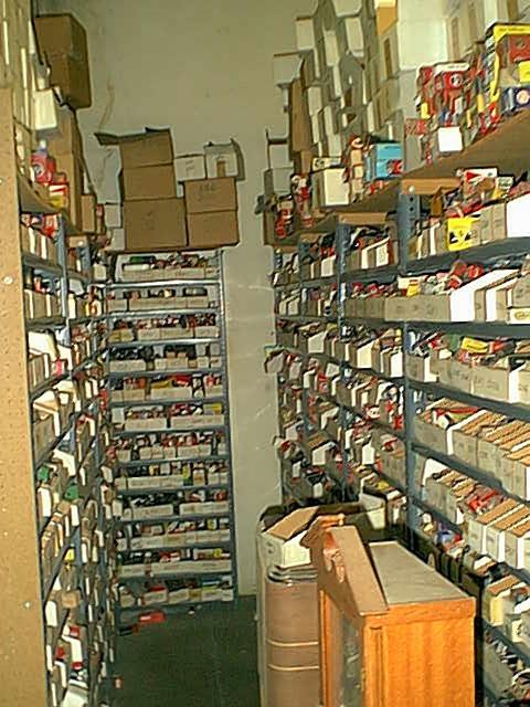
Parts and more tubes.... Don't get
excited about all the
Woodworking supplies (The custom woodworker next
door
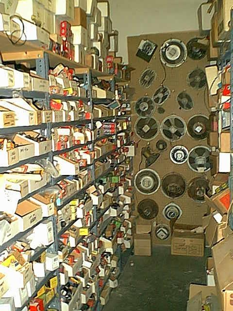
Speakers, they are almost all thrashed. Just in case
I
moved out of state, and gave me tons of bits of exoctic
need one (after reconing)
veneers, etc. Also, 2 racks of "parts sets"
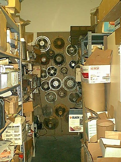
Stuff waiting for "someday"... The
Zenith cabinet has been re-veneered in Japanese Tamo Ash, which will
look really great when
finished.
Pi